Shock Load Profile
"Shock Load Profile" is an ACT application that allows ANSYS Mechanical users to define shock load as an acceleration-time data pair.
In the ANSYS Mechanical interface, the acceleration load can be applied to the entire FE model. In other words, there is no available command to define the acceleration load on any geometric entity. For this reason, in order to define the acceleration-time load, firstly the data calculated according to the relevant standard should be prepared, and then these data should be loaded into the FE model with APDL (ANSYS Parametric Design Language) macros.
However, this method is both time-consuming and may cause user errors. With the "Shock Load Profile" application, user defined shock profiles or custom shock profiles according to BV043–‘Shock Resistance Specification' and MIL-STD-810G can be automatically calculated and easily applied with the selected geometric entities or nodes.
Contact us for more information.
1. Running “Shock Load Profile” ACT
After installation of “Shock Load Profile” extension, a button placed on Mechanical toolbar. By clicking the button, “Shock Load Profile” load object and dummy “Command Snippet” are inserted in outline tree (Figure 1).

Figure 1 - Running “Shock Load Profile”
2. Selecting Geometry
Geometries or nodes can be selected directly or with "Named Selection" method in Geometry branch (Figure 2).

Figure 2 - Selecting geometry/node
3. Defining Shock Profile
User can define a shock profile in three methods (Figure 3):
-
User Defined
-
NATO Standard Level
-
MIL-STD
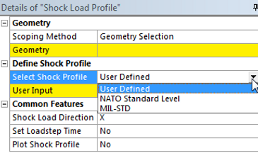
Figure 3 - Defining Shock Profile
-
The custom time-acceleration data set can be defined via “User Defined” method.
-
According to BV043, NATO standard shock profiles can be defined as triangle or double sine distribution methods via “NATO Standard Level” profile.
-
According to MIL-STD-810G, MIL-STD shock profiles can be defined as sawtooth, trapezoidal or half-sine pulse type via “MIL-STD” profile.
3.1 User Defined Shock Profile
User can define the custom time-accelerations data after selecting “User Defined” branch. The values can be directly inserted to “User Input” window from Excel sheet (Figure 4)

Figure 4 - Defining “User Defined” Shock Values
3.2 NATO Standard Level Shock Profile
A shock profile can be defined as double sine (Figure 5) or triangular (Figure 6) distribution method according to BV043.

Figure 5 - NATO Standard Level (Double Sine)

Figure 6 - NATO Standard Level (Triangular)
3.2 MIL-STD Shock Profile
According to MIL-STD-810G, the shock profile can defined with sawtooth (Figure 7), trapezoidal (Figure 8) and half-sine (Figure 9) pulse type.

Figure 7 - NATO Standard Level (Double Sine)

Figure 8 - NATO Standard Level (Triangular)

Figure 9 - NATO Standard Level (Half-sine)